Begin p 0000 for j in 0001 to 1111 loop if j 1111 then p p 1.
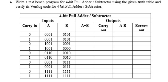
Test bench truth table.
In this tutorial we will create a simple combinational circuit and then create a test bench test fixture to simulate and test the correct operation of the circuit.
There is also a test bench that stimulates the design and ensures that it behaves correctly.
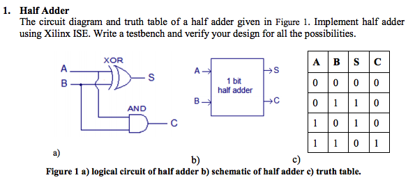
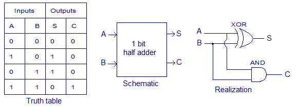
A single half adder has two one bit inputs a sum output and a carry out output.
Process sel variable p std logic vector 3 downto 0.
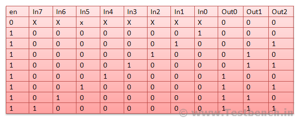
Truth table of simple combinational circuit a b and c are inputs.
The test bench contains statements to apply inputs to the dut and ideally to check that the correct outputs are produced.
Truth table of simple combinational circuit a b and c are inputs.
Next we will write a testbench to test the gate that we have created.
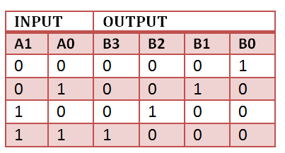
Refer to the truth table below to see how these bits operate.
Using vivado to create a simple test fixture in verilog in this tutorial we will create a simple combinational circuit and then create a test fixture test bench to simulate and test the correct operation of the circuit.
Am i on the right track.
J and k are outputs a b c j k 0 0 0 0 1.
Testbench is another verilog code that creates a circuit involving the circuit to be tested.
A simple truth table will help us describe the design.
B write a vhdl module that implements the function described by the following truth table.
A testbench is an hdl module that is used to test another module called the device under test.
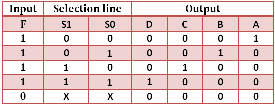
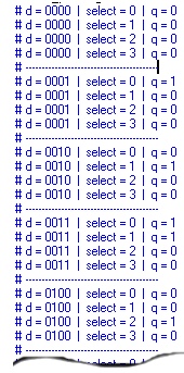
How would i do this in a vhdl test bench to run through a truth table for a multiplexer.
Sel 00 after 100 ns 01 after 200 ns 10 after 300 ns 11 after 400.
а d оооооооо oooppppoooom oooooooolo 0 нон орон орон орона h8 h h h 8 o h 8 8 6 8 8 8 8 1 1 1 1 0 1 1 1 1 1 1 1 1 1 1.
Create a test bench and verify your implementation using simulation.
Save the output waveforms.